




IBEAWUCHI B. ANOKAM
COMPUTER SCIENTIST / ELECTRICAL ENGINEER
Hello, welcome to my online portfolio! I am an M.S. in Computer Science student possessing a B.S. in Electrical Engineering. I pride myself on being a passionate, patient, adaptive, and self-motivated team player who is always ready for a challenge. With roughly 2 years of programming experience and over 6 years of customer service experience, I am seeking a position that will allow me to apply my skills and knowledge to further my professional growth within the scope of Software Development and Engineering.
CODING PORTFOLIO
LISTED HERE ARE A FEW OF MY CODING PROJECTS:
SUMMARY
-
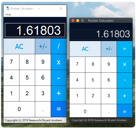
This calculator was developed in C++ using wxWidgets as the GUI toolkit. It performs basic arithmetic calculations. The program includes the all clear, sign change, and decimal point button, which can be coupled with the arithmetic buttons for adding, subtracting, multiplying, and dividing to help the user output their intended integer and decimal calculations.
SPECS
| COMPATIBLE OPERATING SYSTEM(S) | MacOS, Windows | ||
|---|---|---|---|
| CURRENT RELEASE VERSION | 1.0.0 | ||
| SOFTWARE CATEGORY | Calculator | ||
| WRITTEN IN | C++ (wxWidgets) | ||
| COMPATIBLE PERIPHERAL INPUT TYPE(S) | Mouse and Trackpad left-click / left-press | ||
|---|---|---|---|
| - | VALUE RANGE | COMMENTS |
|---|---|---|
| INPUTS | 7-digit 9-character input |
The maximum number of digits the user can input is 7 with the program allowing for an extra 2 characters for the signage and decimal point (if needed) |
| OUTPUTS | ± ( 1.000000 x 10^(-6) ≤ number ≤ 9.99999999 x 10^(8) ) |
The values outputted cannot exceed this range, whether it’s positive or negative version of these values, else an error will be gotten |
APPLICATION IMAGES
SUMMARY
-
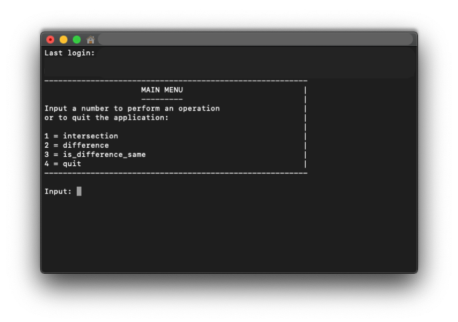
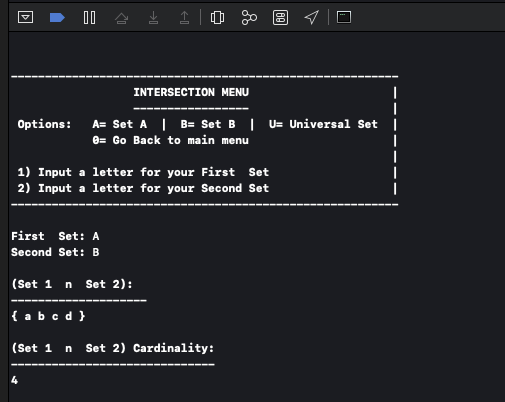
This program computes set operations, intersection and difference, while also allowing the user to check if two difference operations are the same.
SPECS
| COMPATIBLE OPERATING SYSTEM(S) | MacOS / Windows / Linux | ||
|---|---|---|---|
| CURRENT RELEASE VERSION | 1.0.0 | ||
| SOFTWARE CATEGORY | Command Line | ||
| WRITTEN IN | C++ | ||
| COMPATIBLE PERIPHERAL INPUT TYPE(S) | Keyboard | ||
|---|---|---|---|
| - | DESCRIPTION | COMMENTS |
|---|---|---|
| INPUTS | .txt files |
These are the “Set U”, “Set A”, and “Set B” text files – the universal set and the two other sets which will be analyzed. These text files are needed to hold the information in which you will be analyzing |
| OUTPUTS | .txt file |
The text file is needed to output the information found after performing the user operation(s) |
APPLICATION IMAGES
SUMMARY
-
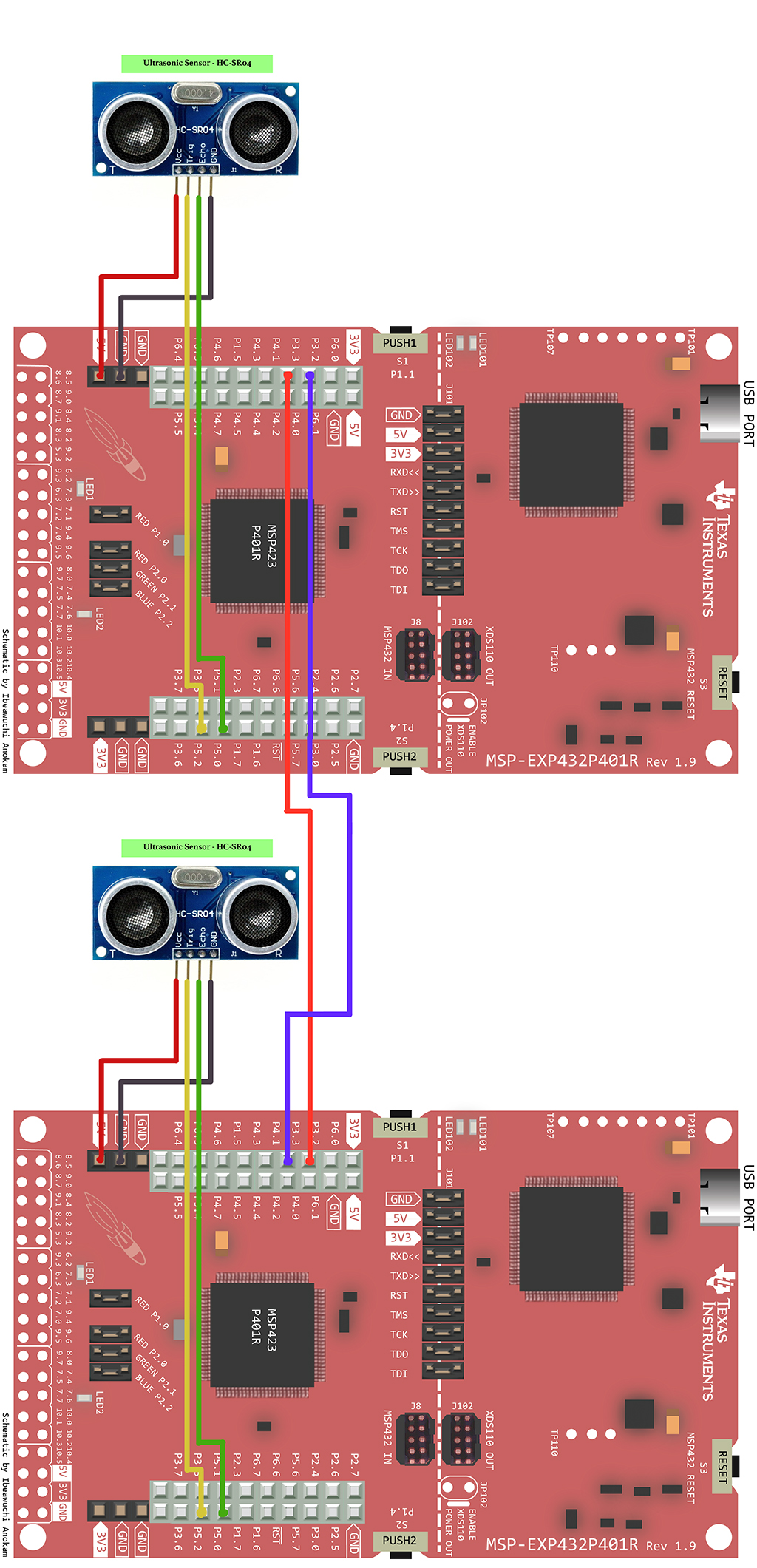
As the MSP432 runs the ultrasonic sensor begins to check if any object is in range of
its sensors. Once an object is 2 to 400 centimeters in range of the sensor it begins
to measure the distance of the object in units of centimeters. Each MSP432 board
transmits the distance of their corresponding ultrasonic sensor to the adjacent board,
which then receives and outputs that given distance onto its serial monitor.
COMPONENTS
| MICROCONTROLLER |
|---|
| TEXAS INSTRUMENTS’ MSP432P401R LAUNCHPAD |
| COMPILER | LANGUAGE |
|---|---|
| ENERGIA v1.6.10E18 | C/C++ BASED |
| ELEMENT / COMPONENT / SENSOR | FUNCTION | SCHEMATIC | CONNECTION METHOD / PROTOCOL |
|---|---|---|---|
| MICRO-USB CABLE | UNIVERSAL SERIAL BUS: USED TO CONNECT MICROCONTROLLER TO A SOURCE OF POWER (i.e. PC) & TO PASS I/O DATA THROUGH IT | 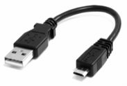 |
SERIAL PORT CONNECTION |
| ULTRASONIC SENSOR - HC-SR04 | ULTRASONIC TRANSDUCER: A TRANSCEIVER THAT TRANSMITS AN ULTRASOUND SIGNAL AND THEN RECEIVES BACK THE SIGNAL CONVERTING IT INTO AN ELECTRICAL SIGNAL. BY MEASURING THE TIME BY WHICH IT TAKES TO SEND AND RECEIVE A SIGNAL THE DISTANCE OF AN OBJECT CAN BE MEASURED. | 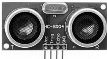 |
PIN HEADER CONNECTION BY 4-PIN “BERGE CONNECTOR” |
| 3 PIN FEMALE/MALE 'EXTENSION' JUMPER WIRES | COMPONENT CONNECTOR | 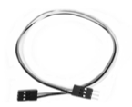 |
PIN HEADER CONNECTION |
COMPONENT SPECS
| ULTRASONIC SENSOR - HC-SR04 | MINIMUM | TYPICAL | MAX | UNIT |
|---|---|---|---|---|
| SUPPLY VOLTAGE (VCC) | - | 5.00 | - | VDC |
| SUPPLY CURRENT (ICC) | - | 15.00 | - | mA |
| WORKING FREQUENCY | 40 | HZ | ||
| DETECTING DISTANCE | 2 | ~ | 400 | cm |
| MEASURING ANGLE | 15 | degrees | ||
| RANGING ACCURACY | 3 | mm | ||
| TRIGGER INPUT SIGNAL | 10 | μs (TTL Pulse) | ||
| ECHO OUTPUT SIGNAL | Input TTL lever signal and the range in proportion | - | ||
SCHEMATIC DIAGRAM
CODE
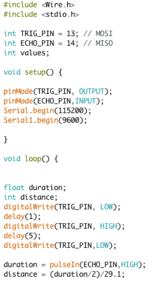
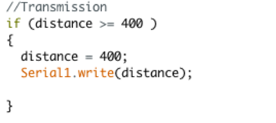
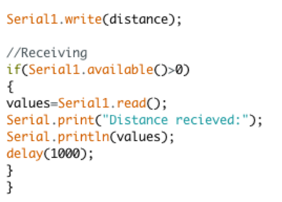
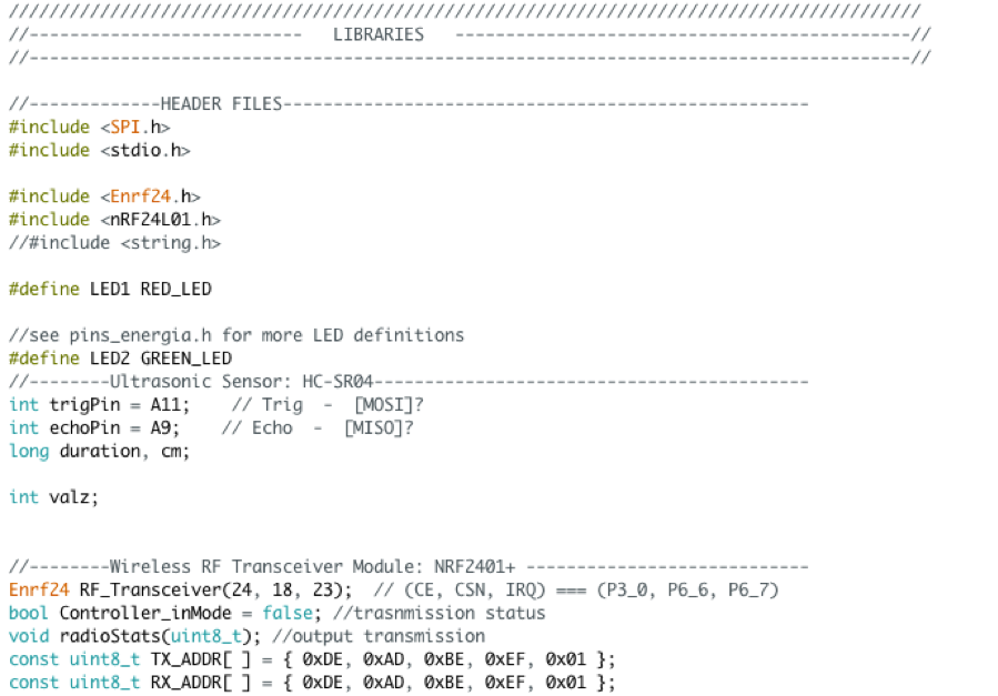
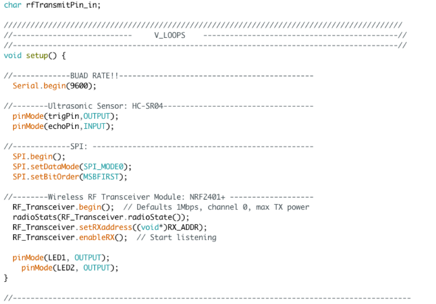
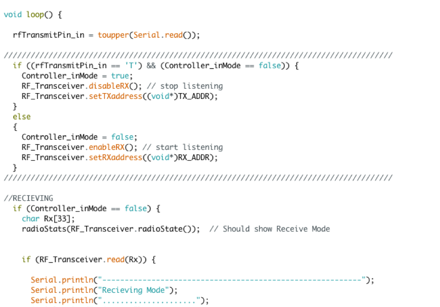
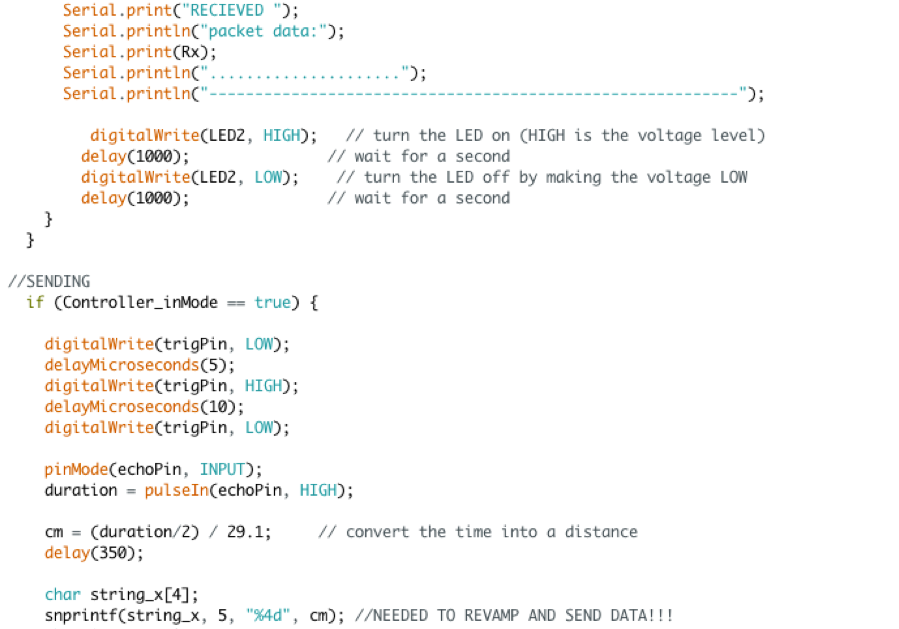
SUMMARY
-
As the MSP432 is running the ultrasonic distance sensor begins to check if any
object is in range of its sensors. Once an object is 2 to 400 centimeters in
range of the sensor it begins to pick up the signal. When one person enters a
“T” on their serial monitor and sends it the ultrasonic distance sensors signal
from that person’s board is then sent to the serial monitor of any MSP432 board
that is in wireless distance of the NRF2401+ 2.4GHz wireless RF transceiver module.
Once sent to the other person the module picks up the signal with the distance and
displays the measured distance of the object from the other persons MSP432 onto
their serial monitor.
COMPONENTS
| MICROCONTROLLER |
|---|
| TEXAS INSTRUMENTS’ MSP432P401R LAUNCHPAD |
| COMPILER | LANGUAGE |
|---|---|
| ENERGIA v1.6.10E18 | C/C++ BASED |
| ELEMENT / COMPONENT / SENSOR | FUNCTION | SCHEMATIC | CONNECTION METHOD / PROTOCOL |
|---|---|---|---|
| MICRO-USB CABLE | UNIVERSAL SERIAL BUS: USED TO CONNECT MICROCONTROLLER TO A SOURCE OF POWER (i.e. PC) & TO PASS I/O DATA THROUGH IT | |
SERIAL PORT CONNECTION |
| ULTRASONIC SENSOR - HC-SR04 | ULTRASONIC TRANSDUCER: A TRANSCEIVER THAT TRANSMITS AN ULTRASOUND SIGNAL AND THEN RECEIVES BACK THE SIGNAL CONVERTING IT INTO AN ELECTRICAL SIGNAL. BY MEASURING THE TIME BY WHICH IT TAKES TO SEND AND RECEIVE A SIGNAL THE DISTANCE OF AN OBJECT CAN BE MEASURED. | |
PIN HEADER CONNECTION BY 4-PIN “BERGE CONNECTOR” |
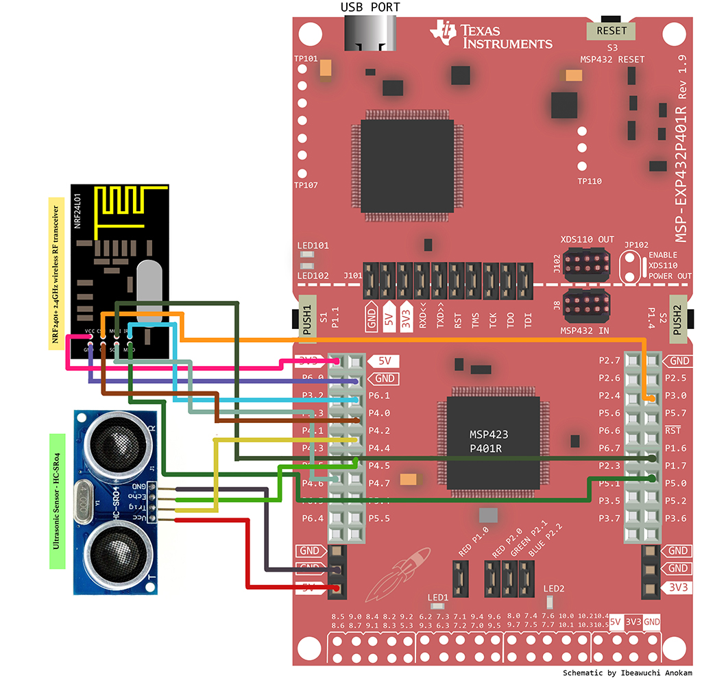
| NRF2401+ 2.4GHZ WIRELESS RF TRANSCEIVER MODULE | WIRELESS RF (RADIO FREQUENCY) TRANSCEIVER MODULE: TRANSMITS AND RECEIVES RADIO SIGNALS BETWEEN TWO DEVICES OPERATING ON THE 2.4GHZ ISM BAND | SERIAL PERIPHERAL INTERFACE BUS (SPI) PIN HEADER CONNECTION | |
| 3 PIN FEMALE/MALE 'EXTENSION' JUMPER WIRES | COMPONENT CONNECTOR | |
PIN HEADER CONNECTION |
COMPONENT SPECS
| ULTRASONIC SENSOR - HC-SR04 | MINIMUM | TYPICAL | MAX | UNIT |
|---|---|---|---|---|
| SUPPLY VOLTAGE (VCC) | - | 5.00 | - | VDC |
| SUPPLY CURRENT (ICC) | - | 15.00 | - | mA |
| WORKING FREQUENCY | 40 | HZ | ||
| DETECTING DISTANCE | 2 | ~ | 400 | cm |
| MEASURING ANGLE | 15 | degrees | ||
| RANGING ACCURACY | 3 | mm | ||
| TRIGGER INPUT SIGNAL | 10 | μs (TTL Pulse) | ||
| ECHO OUTPUT SIGNAL | Input TTL lever signal and the range in proportion | - | ||
| NRF2401+ 2.4GHZ WIRELESS RF TRANSCEIVER MODULE | MINIMUM | TYPICAL | MAX | UNIT |
|---|---|---|---|---|
| SUPPLY VOLTAGE (VCC) | 1.9 | ~ | 3.6 | VDC |
| INPUT/OUTPUT PIN WORKING VOLTAGE (ICC) (Vcc=3.3 V) | 3.3 | 5.0 | VDC | |
| TRANSMISSION RATE | +7 | dB | ||
| RECEIVING SENSITIVITY | ≤-90 | dB | ||
| TRANSMISSION RANGE (CLOSED AREA) | 50 | ~ | 60 | m |
| TRANSMISSION RANGE (OPEN AREA) | 50 | ~ | 100 | m |
SCHEMATIC DIAGRAM
CODE
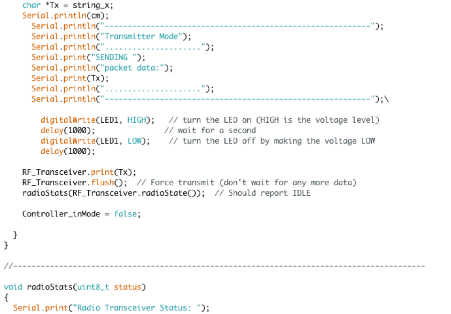
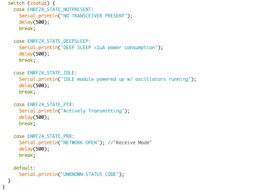
SUMMARY
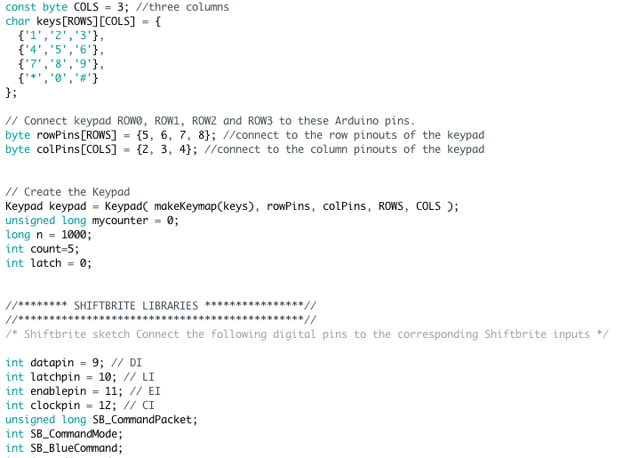
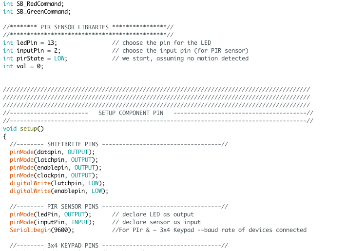
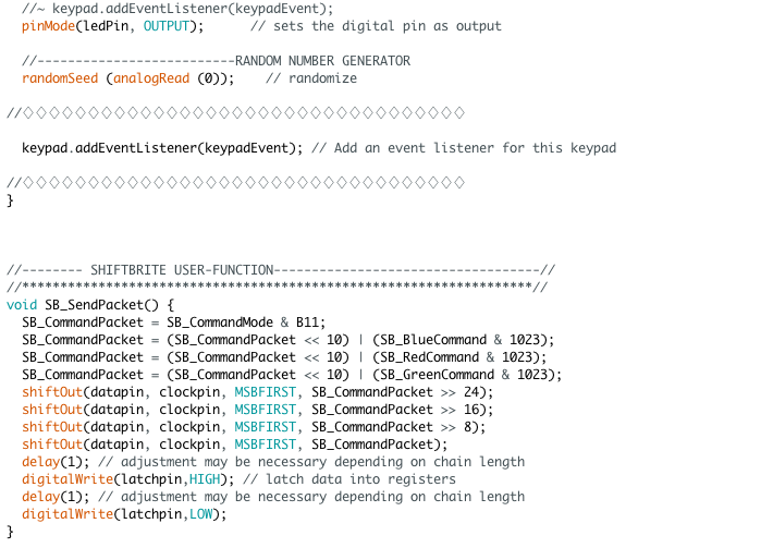
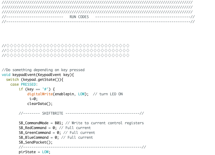
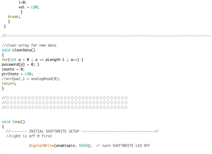
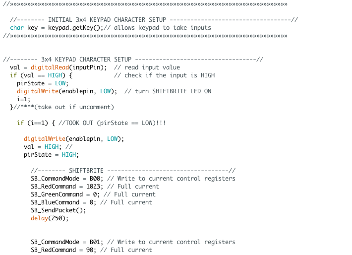
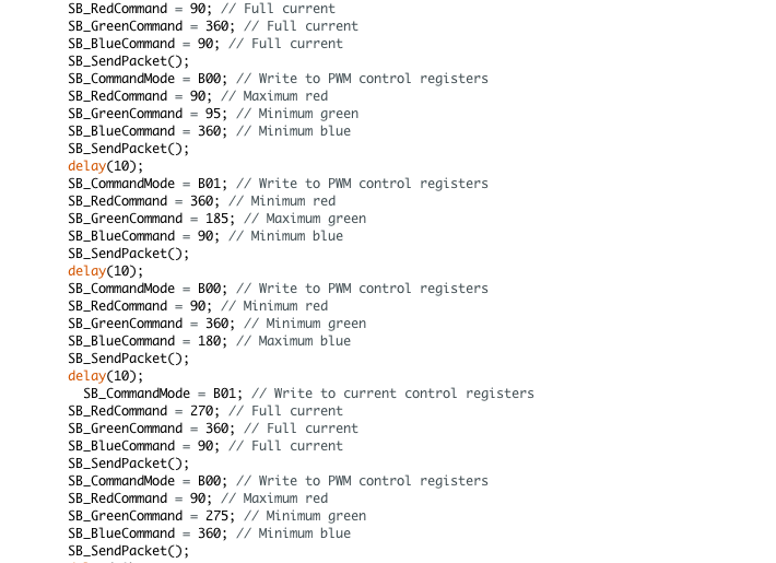
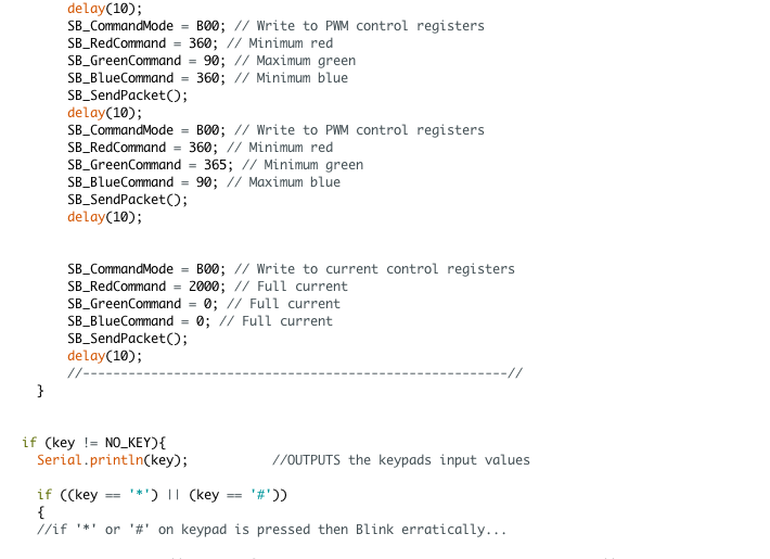
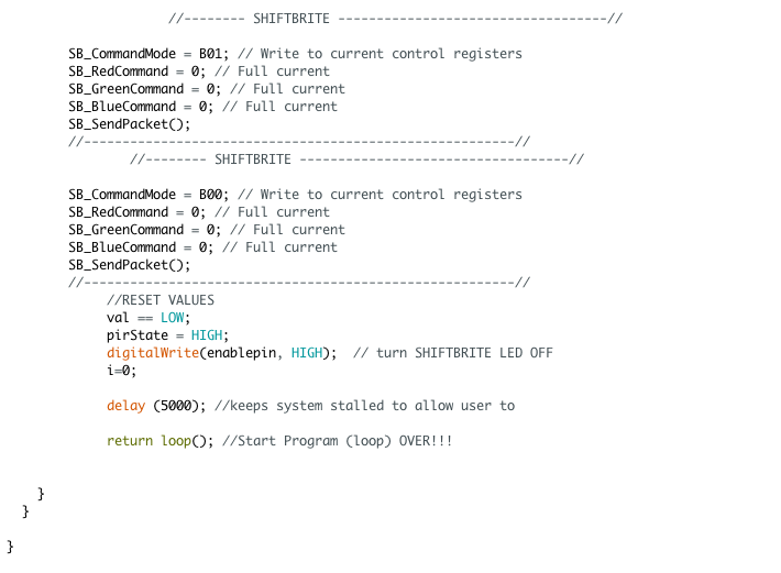
- Created a PIR motion sensor security system with an
Arduino Uno microcontroller which is triggered when a body
is in range of the detecting area
COMPONENTS
| MICROCONTROLLER |
|---|
| ARDUINO UNO REV3 A000066 |
| COMPILER | LANGUAGE |
|---|---|
| ARDUINO v1.6.11 | C/C++ BASED |
SCHEMATIC DIAGRAM
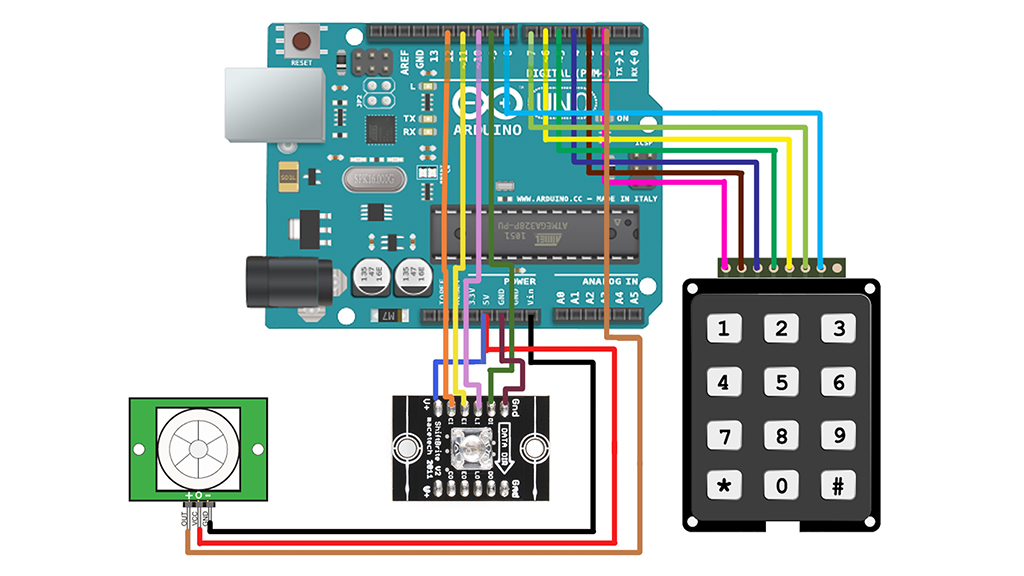
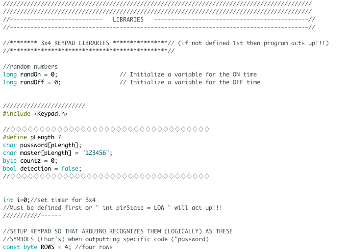
CODE
SUMMARY
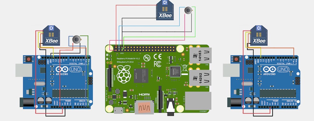
- Using the Raspberry Pi as the main microcontroller,
in conjunction with two Arduino Uno’s, this project proposes
a method to set an accurate and efficient, energy-saving
solution to control the temperature of a room. By acquiring
the parameters of temperature inside and outside of the room with sensors
we can get a series of appropriate control signals to control
the heater ensuring a comfortable temperature is kept within the room. This proposed
system of ours can greatly reduce energy consumption and ensure
real-time monitoring of the room while giving the end-user the
required room temperature he or she needs.
ROLES:
- Team captain
- Budgeting
- Programmer:- Modeled with Raspberry Pi Zero in Python in a Linux environment
- Modeled with Arduino Uno in C/C++ environment
COMPONENTS
| MICROCONTROLLER |
|---|
| ARDUINO UNO REV3 A000066 |
| COMPILER | LANGUAGE |
|---|---|
| ARDUINO v1.6.11 | C/C++ BASED |
| MICROCONTROLLER |
|---|
| RASPBERRY PI 2B |
| COMPILER | LANGUAGE |
|---|---|
| PYTHON 3 | PYTHON |
SCHEMATIC DIAGRAMS
MICROCONTROLLER DESIGNS
WIRELESS SENSOR NETWORK (WSN) DESIGN
DATA LOGGING
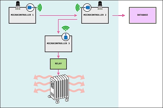
Two microcontrollers pick up the temperature in the room from its two opposing sides and then send the averaged temperature to the third microcontroller, which will then begin to change the temperature of the room by controlling the heater using Pulse Width Modulation (PWM) modulation to vary the average power delivered to the device. A PID control voltage will be used to set Pulse Width Modulation.
PHOTOGRAPHY PORTFOLIO
I AM NOT ONLY PASSIONATE FOR PROGRAMMING BUT ALSO HAVE AN EYE FOR ART TOO!
LISTED BELOW YOU'LL FIND A FEW PIECES OF WORK FROM MY HOBBY AS A PHOTOGRAPHER:








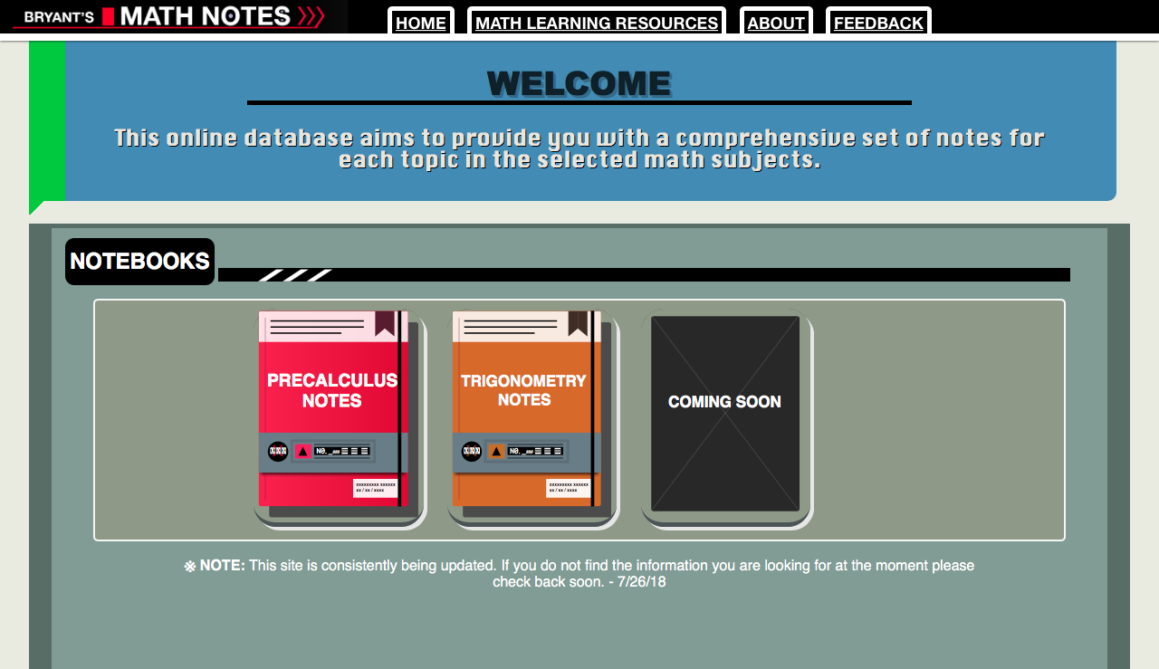
MATH WEBSITE (EXTERNAL LINK)
HERE IS MY MATH WEBSITE. THE PROJECT IS STILL UNDER CONSTRUCTION.